You’re running a three-layer co‑extrusion line to produce high‑quality film while keeping material costs down. The concept is straightforward: two extruders feed a die that arranges the melt into an A‑B‑A structure, with the core B layer containing up to 70% calcium carbonate or recycled content. The outer A layers stay pure, giving you good surface properties, sealing characteristics, and printability at a fraction of the cost of monolayer virgin film.
But any technician who has operated an ABA film blowing machine knows that theory and practice don’t always align. Bubbles wobble. Die lips carbonize. Thickness ratios drift. Gearboxes groan. This FAQ‑style guide answers the questions that come up most often on production floors — from bubble instability to maintenance schedules — based on real experience with Zhuxin Machinery’s ABA CO‑EX AUTO line.
Bubble stability and melt strength
Q1: Why does my ABA bubble keep wobbling even when temperatures look correct?
The most common cause is inconsistent melt strength between the three layers. In an A‑B‑A structure, the core B layer (with calcium carbonate or recycled material) has lower melt elasticity than the virgin outer A layers. If the temperature of the B extruder drifts even 5–10°C above the optimal range, the core becomes too fluid, and the outer layers can’t maintain the bubble’s structural integrity.
Checklist to stabilize the bubble: Verify that barrel zone temperatures for the core extruder are within ±1°C of setpoint. For LDPE‑based CaCO₃ blends (20–50% filler), aim for 190–210°C. If temperature is stable but wobble persists, reduce the core extruder’s screw speed by 10–15%. This increases melt residence time, improving mixing and restoring melt strength. Also make sure the air ring is clean and that cooling airflow is balanced all around the bubble — uneven cooling is a frequent hidden cause.
Q2: How can I tell if the problem is in the core layer or one of the outer layers?
Perform a simple “peel test” after shutdown. Pull a film sample and manually separate the three layers. If the middle layer feels brittle or crumbly, the calcium carbonate content is too high or mixing is incomplete. If the outer layers peel off with visible thickness variation, the extrusion ratio between the two A‑layer extruders is unbalanced. Install melt pressure sensors before the die; fluctuating pressure (more than ±5% of setpoint) points to inconsistent feeding from the gravimetric hopper or worn screw flights.
Diagnosing bubble oscillation patterns
Oscillation frequency gives clues. A slow, wobbly bubble (1–2 cycles per second) usually indicates melt temperature problems. A high‑frequency flutter (5–10 Hz) points to airflow issues — clean the air ring and check for debris in the cooling slots.
Die lip buildup and carbon deposits
Q3: Why does my ABA machine develop black specks in the film after running for several hours?
The middle B layer contains calcium carbonate or recycled material, which has lower thermal stability than virgin resin. At the adapter block where the three melt streams merge, material can stagnate in “dead zones” of the flow channel, degrade, and carbonize. These carbon specks eventually break loose and stick to the die lip, causing dark streaks in the film — called “die lines.”
Prevention: Schedule daily lip cleaning during continuous runs. For high‑CaCO₃ blends, lower the die temperature by 5–10°C relative to the barrel zones. Ensure your die head uses a “first‑in, first‑out” spiral mandrel design that eliminates stagnant areas. Once a week, run a commercial purge compound through both extruders at normal operating temperature for 3–5 minutes. Some processors also pull the screen pack during purging to flush degraded residues trapped in the breaker plate.
Q4: What’s the fastest way to clear die lip buildup without shutting down?
For minor buildup, some operators use a brass scraper or wooden stick to gently wipe the lip while the machine runs — but this is risky and requires experience. A safer method: reduce line speed by 30–40%, which lowers the melt pressure and allows carbon specks to pass through without sticking. Run at reduced speed for 10–15 minutes, then gradually accelerate back to normal. If buildup recurs within an hour, schedule a full die cleaning.
Gearbox maintenance and abnormal noise
Q5: My ABA line has two gearboxes — one for the core extruder, one for the outer extruders. How do I know which one is failing?
Listen for a low‑frequency “knocking” or “thumping” sound, especially at low screw speeds. That often indicates a worn bearing or a cracked gear tooth. Use a mechanic’s stethoscope to probe each gearbox housing. If the noise coincides with melt pressure spikes on the HMI trend chart, the problem is mechanical. Shut down immediately and drain the gear oil. Look for metal flakes or a silvery sheen — that confirms internal wear.
Preventive schedule for 24/7 operations: Change gearbox oil every 3,000 operating hours using ISO VG 220 synthetic oil. Monthly, send an oil sample for ferrography analysis to detect microscopic wear particles before bearing failure becomes audible. Also check gearbox alignment with a dial indicator; misalignment accelerates bearing wear.
Extruder screw and barrel wear
Calcium carbonate is abrasive. Over time, it wears the screw flights and barrel inner wall, especially in the mixing zone. A worn screw reduces output and causes uneven layer thickness. Measure screw outer diameter annually and compare to original spec. If the screw has lost more than 0.2 mm in diameter, plan for replacement or hard‑facing rebuild.
Layer ratio drift and material savings
Q6: I’ve set my A and B extruder speeds for a 20/60/20 layer ratio. After a week, the ratio changes. Why?
The two extruders have independent screw speed controls, but their relationship is based on assumed melt densities at the time of setup. Over time, thermocouples drift, heater bands age, and the actual melt density changes. The same screw speed then delivers a different mass flow rate. If the B layer ratio drifts downward (say from 60% to 45%), you’re wasting expensive virgin resin. If it drifts upward, film strength and seal quality suffer.
How to restore the ratio: Stop the line and take a film cross‑section under magnification. Measure the three layers at five positions across the width. Calculate the actual volumetric ratio, then adjust the screw speed setpoints proportionally. For long‑term stability, invest in gravimetric dosing units on each extruder — they measure actual mass flow in real time and maintain the ratio automatically, paying for themselves in material savings within months.
Q7: How precise does temperature control need to be for stable layer ratios?
For an ABA line, maintain barrel zone temperatures within ±1°C of setpoint. Standard controllers with ±5°C accuracy (common on older machines) allow ratio drift because melt viscosity changes with temperature. If your HMI shows temperature swings, check thermocouple placement — they should be embedded in the barrel wall, not clamped on the surface. Loose heater bands also create hot spots that degrade the core layer and alter melt viscosity.
Below is a quick reference table for common ABA faults and their likely causes:
| Symptom |
Most Likely Cause |
Diagnostic Check |
| Bubble wobbles at all speeds |
Core layer temperature too high |
Check B extruder barrel zones |
| Intermittent wobble (comes and goes) |
Inconsistent CaCO₃ feeding |
Clean gravimetric hopper throat |
| Dark specks in film |
Degraded polymer at die lip |
Daily lip cleaning; purge compound |
| Machine‑direction streaks |
Die lip buildup or worn die land |
Inspect lip with magnifying glass |
| Cross‑web thickness variation |
Uneven cooling air flow |
Clean air ring; balance slots |
| Knocking noise from gearbox |
Bearing or gear tooth wear |
Stethoscope probe; check oil |
| Outer layers too thick (ratio shift) |
Thermocouple drift on A extruder |
Calibrate thermocouples |
| Gritty film surface |
CaCO₃ migration to outer layer |
Reduce B screw speed; lower die temperature |
Calcium carbonate mixing and filler distribution
Q8: My ABA film feels rough or has visible “fish eyes.” What’s wrong?
Calcium carbonate particles agglomerate if they aren’t pre‑dispersed properly. Standard 24:1 L/D screws are often insufficient for high‑filler compounds (50–70%). Dedicated ABA machines use 30:1 or 32:1 L/D screws with barrier mixing sections to break up agglomerates. Also verify that your CaCO₃ masterbatch is dry — excess moisture creates steam pockets that disrupt mixing and cause fisheyes.
Immediate fix: Increase the barrel temperature in the mixing zone by 5–10°C to lower melt viscosity and improve dispersion. If the problem persists, switch to a pre‑compounded CaCO₃ masterbatch rather than adding filler at the hopper. For biodegradable resins (PLA/PBAT), keep CaCO₃ loading below 30% — higher levels make the film brittle and non‑compostable.
Q9: Can I run recycled material in the B layer of an ABA machine?
Yes, that’s one of the main advantages. Recycled post‑industrial or post‑consumer polyethylene can be used in the core layer at levels of 30–70%, depending on the final application. However, recycled material often has higher contamination (paper, adhesive, different melt indexes). Install a melt filter (screen changer) after the B extruder and change screens more frequently — every 2–4 hours instead of daily. Also run a smaller mesh screen (e.g., 150 mesh instead of 80 mesh) to catch contaminants that would otherwise create gel specks in the film.
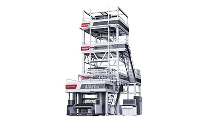
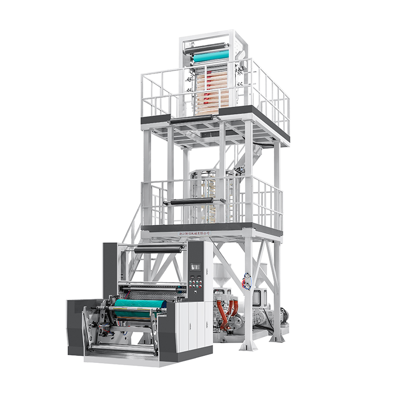
How Zhuxin Machinery’s ABA CO‑EX AUTO addresses these issues
The ABA CO‑EX AUTO Film Blowing Machine from Zhuxin Machinery is designed to minimize the five common problems discussed above.
Bubble stability: The intelligent tension closed‑loop system maintains yield rates above 99% even for ultra‑thin films down to 0.01 mm — critical for daily chemical packaging and agricultural films where downtime destroys margins.
Material savings: The ABA structure reduces center layer barrier material consumption by 40% while increasing tear strength by 50% compared to monolayer films of the same thickness. The homogenized surface layer design prevents edge curl, especially important for elastomers like TPU and PE.
Specifications at a glance: Film width range 600–1200 mm, thickness range 0.02–0.10 mm, maximum output HDPE 120 kg/hr, LDPE 180 kg/hr. Screw diameters φ55 and φ65. Compatible materials: HDPE, LDPE, LLDPE, CaCO₃ filler, PLA, PBAT, PVA — covering standard and biodegradable formulations.
Maintenance-friendly design: Open‑access cabinets allow daily gearbox oil level checks without removing panels. The die head uses streamlined “first‑in, first‑out” channels that reduce dead zones where carbon deposits form.
Before you place a bulk order, request a factory acceptance test using your actual CaCO₃ blend ratio and target film thickness. Watch the bubble for a full shift. Check for black specks and fisheyes. Measure layer ratio stability hour by hour. A few hours of validation prevents years of troubleshooting.
Ready to cut material costs with an ABA co‑extrusion line? Contact Zhuxin Machinery for a custom ABA CO‑EX AUTO configuration based on your target layer ratio (e.g., 20/60/20, 15/70/15), filler percentage, and output requirement. Their technical team can provide die gap recommendations, temperature profiles, and a sample film roll before you buy.