You’ve just pulled a roll off the winder. The edges look fine, but running your hand across the surface reveals a thick band that repeats every few meters. Or maybe the gauge drifts from one side to the other. Inconsistent thickness doesn‘t just affect appearance—it weakens seal strength, creates baggy lanes, and wastes raw material. On a 5 Layers Film Blowing Machine, the complexity of five independent extruders feeding one die means more potential failure points. This guide walks through a structured approach to thickness variation: reading the pattern, checking mechanical alignment, balancing the air ring, stabilizing layer ratios, and diagnosing material issues.
What the thickness pattern tells you before you touch anything
Fixed localized thick spot. The film has a thick band that stays at the same circumferential position as the die rotates. This points to a die lip defect—a scratch, debris buildup, or a localized gap error. If the die is equipped with a rotating or oscillating haul‑off system, a fixed position thick band that moves with die rotation indicates the issue is upstream of the rotating section.
Single-side thicker (wedge profile). One side of the film consistently measures thicker than the opposite side. The air ring is not concentric with the die, causing uneven cooling around the bubble circumference.
Circumferential periodic wave. Thick and thin sections alternate around the bubble circumference in a repeating pattern. The air ring has uneven airflow—blocked discharge slots, a misaligned lip, or unbalanced blower output.
Random spike. Isolated thick spots appear without a consistent pattern. The melt contains contamination, degraded polymer particles build up on the die lip and periodically break loose, or screen pack needs changing.
Mechanical checks that fix most fixed-position problems
Die lip gap. Use a feeler gauge to measure the die lip gap at 8 to 12 points around the circumference. All measurements should be identical within 0.02–0.05mm. If a local area consistently shows a wider or narrower gap, the adjusting bolts on that segment need correction. Clean die lips with a soft copper blade—never steel—to remove burnt polymer residue, resin buildup, or degraded material that creates localized flow restriction.
Die heaters. Use an infrared thermometer to measure die body temperature at multiple points around the circumference. Each zone should be within ±3°C of setpoint. A dead heater band creates a cold segment where melt viscosity increases, flow resistance rises, and the exiting film becomes thinner in that sector. Replace any heater that fails to reach setpoint or cycles abnormally.
Rotating haul-off vibration. Check the rotating haul-off unit for smooth operation during production runs. Excessive vibration transfers to the collapsing frame, where it can compress the bubble unevenly or cause fluttering that shows up as gauge variation. Inspect bearings and drive belts according to manufacturer intervals.
Where cooling symmetry matters most
The air ring is the most common source of circumferential thickness variation after the die itself has been verified. The bubble must receive even cooling around its entire perimeter; otherwise, differential cooling rates change the draw‑down ratio around the circumference.
Centering check. The air ring must be concentric with the die. A gap variation as small as 0.5mm produces uneven cooling. Adjust the centering bolts until the gap measured at four points 90° apart is uniform.
Airflow balancing. Dust, polymer fines, and degraded residue can partially block air ring discharge slots. With the machine running at low speed, use a smoke pencil or a strip of tissue paper around the air ring exit to visualize flow. Strong flow at one point and weak at another confirms an imbalance. Clean all discharge slots and air passages with compressed air, then rebalance by adjusting individual zone dampers on the air ring control panel.
Frost line height consistency. The frost line—the boundary where the molten polymer transitions to solid—should be at the same height around the entire bubble circumference. An uneven frost line directly translates to uneven thickness. If one side of the bubble frosts higher, the air ring is not concentric or individual airflow zones are imbalanced.
The advantage of modern IBC and rotating systems
Advanced lines include IBC (internal bubble cooling) and rotating haul‑off systems that reduce thickness variation. IBC uses air blown inside the bubble to cool the film from the interior, improving bubble stability and thickness uniformity while reducing energy consumption per kilogram. Automated gauge control uses closed‑loop thickness measurement to correct output. Zhuxin‘s 5‑layer line includes IBC, precise melt pump control, and a rotating haul‑off designed for 360° continuous bidirectional rotation. The rotating haul‑off averages any remaining gauge variation across the roll width, distributing localized thick bands across the roll’s surface rather than concentrating them in one lane.
Layer ratio drift — the 5‑layer specific trap
In a five‑layer structure (typically A/B/C/B/A or functional variations), each extruder contributes a specific percentage of total thickness. If one extruder‘s output drifts, the layer ratio changes—and with it, the overall thickness distribution.
Checking ratio stability. Most controllers display individual extruder screw speeds and calculated outputs. Compare current readings against the baseline values for each layer at the time of last successful setup. If one extruder’s speed has drifted more than ±2 RPM while others remain stable while maintaining the same total output, the drift may indicate worn screw sections or degraded material.
Isolating the problem layer. The “stop‑layer” technique can isolate a suspect extruder. Briefly reduce the output of one extruder by 5% while maintaining others, then observe thickness profile changes. If the thick band shifts dramatically, that layer is contributing to the variation. After diagnosis, restore settings immediately to avoid scrap.
Melt pump synchronization. The Zhuxin line uses precise melt pump control to maintain layer thickness uniformity error within ≤3%. If the master controller shows inconsistent melt pump speeds across the five extruders, recalibrate the drive parameters according to the manual.
When material consistency becomes the hidden variable
Melt flow index mismatches cause flow instability. Each extruder should run a resin with compatible MI. If the raw material supplier sends a batch with significantly different MI, layer flow rates change at the same extruder settings.
Regrind percentage changes. Recycled material flows differently than virgin resin. If regrind percentage suddenly increases, thickness profiles may shift. Verify regrind addition rate against standard formula. For consistent quality, regrind should be dried and screened to remove fines before reintroduction.
Mixing and contamination. Inadequate blending of color masterbatch or additives creates local viscosity changes. Check mixing equipment and verify that additive feeders are dispensing at correct rates.
Quick reference for thickness issues
| Pattern |
Most Likely Cause |
First Check |
| Fixed localized thick spot |
Die lip damage or debris |
Clean die lips, check gap |
| Side-to-side wedge |
Air ring not centered |
Recenter air ring |
| Circumferential wave |
Uneven airflow |
Clean air ring slots |
| Random spike |
Contamination or degraded polymer |
Check screen pack pressure |
| Periodic band (rotates with die) |
Die temperature zone dead |
IR check of die heaters |
| Thick edges, thin center |
Insufficient blow‑up ratio |
Increase BUR toward 2.5–3.0 |
The Zhuxin line‘s precise melt pump system maintains layer thickness uniformity error ≤3%, significantly reducing raw material costs by 15%+ compared to lines without active gauge control. The 5‑layer structure supports ultra‑high barrier, puncture resistance, and weather resistance for demanding packaging applications.
Questions from production floors
Can uneven thickness be fixed online without stopping production? Yes—air ring adjustments and minor die bolt tweaks can be made while running. However, major die cleaning or heater replacement requires stopping the line. Use rotating haul‑off to average out minor variations during operation.
How often should die gap be recalibrated? At least once per week on continuous lines. After any die cleaning, always remeasure and adjust. For lines running highly filled compounds or recycled material, check daily.
Does higher layer count make thickness control harder? Not necessarily. Five‑layer dies offer more flexibility to hide recycled material in inner layers without affecting surface properties. However, more extruders mean more potential sources of drift. The Zhuxin modular design supports flexible combination of PE/PP and other multi‑materials for optimized barrier structures while maintaining thickness uniformity through precise melt pump control.
Is a thicker skin layer better for barrier performance? No. Barrier properties depend on the composition of the core layer (e.g., EVOH, nylon, or specialized polyolefins) and the tie layers that bond dissimilar materials. Skin layers should be just thick enough to provide mechanical protection and sealability. The co‑extrusion die‘s flow channel design ensures each layer maintains its intended thickness contribution across the full width.
Handling variation that won‘t go away
If all checks pass but thickness variation persists, the issue may be deeper than field adjustments. Potential root causes include worn die internals from abrasive fillers, extruder thrust bearing wear causing screw axial movement, or electrical control system drift. Contact the machinery manufacturer before disassembling major components.
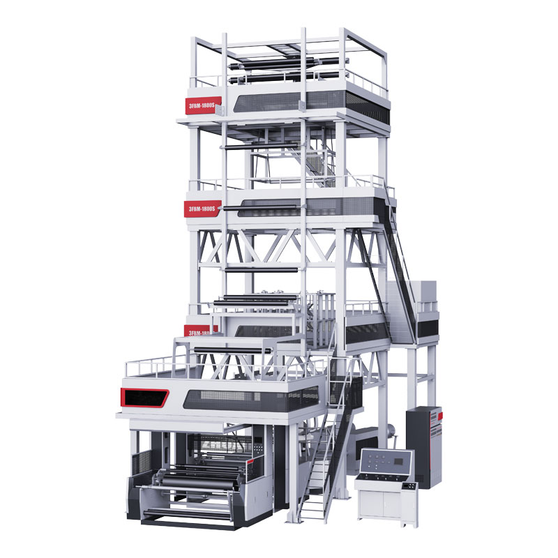
The 5 Layers Internal Bubble Cooling FFS Film Blowing Production Line from Zhuxin is engineered to minimize thickness variation through German‑standard precision transmission systems, modular co‑extrusion die design, and precise melt pump control with ±3% thickness uniformity error. The line produces film width up to 1000mm, thickness from 0.10mm to 0.25mm, with maximum output of 250‑300 kg/h. Screw configuration is A:Φ55 B:Φ55 C:Φ65 D:Φ55 E:Φ55. With 80% energy saving and efficiency improvement, Zhuxin has over 2,000 successful cases worldwide since 1989.
→ Request a quote from Zhuxin for the 5 Layers Internal Bubble Cooling FFS Film Blowing Production Line — Share your target film width, thickness range, and output requirements. Their technical team can provide line configuration and process optimization recommendations.